A whole lotta diode. December 16, 2007
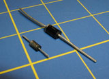
 I received my order from Electronics Goldmine late last week. It contained, among other things, a couple of items for the Motor Controller Project: several 3″x4″ pieces of copper-clad board and twenty 1N5404 diodes (3A, 400V). I knew these were overkill, but I figured it was safer to err on the side of caution.
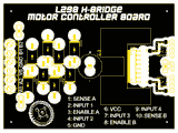
What I hadn’t figured was the physical size of the new diode. In my original board layout, I’d used 1N4004 diodes, only because they were what I had on-hand. The 1N5404 are more than twice the width and time-and-a-half longer than I’d planned. I tried cramming one onto my mockup of the board (a printed copy on cardboard) and failed ridiculously.
So: the board needed to be redesigned.
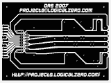
 The copper-clad I ordered was larger than I needed for the original design; this worked to my advantage. With the extra space, the new board was easy to lay out. I decided to make the traces heavier, which also simplifies things. I still find Eagle frustrating, so I ended up doing a lot of touch-up in Photoshop. The most significant edit I made was reducing the diameter of the holes. I wanted to make them only tiny dots in the copper, much smaller than the hole, serving only as guides for the drill.
The copper-clad is also double sided, something I hadn’t thought about. Rather than etch it all away, I’m going to try doing a double-sided board. Most of the top has no functional purpose. I gave each hole a wide radius in order to account for misalignment between the sides. The connection to the first and last input (on the right side) was made via a jumper wire in the original design; I’m going to attempt running a trace on top. I can’t do a plated through-hole, so I’m planning to put wire through the hole, solder each side, then cut the wire flush with the solder blob. I’m not sure if this is the recommended way of doing a home-brew via, but it’s worth a shot. If things turn out badly in the etch, I’ll just revert to the jumper wire idea.
Once I have access to a laser printer (i.e. the office on Monday), I’ll print a few copies on magazine paper. It seemed to work fairly well last time. If I see any smudging of the toner after the transfer, I’ll dissolve it with acetone and try again.
Leave a Reply
You must be logged in to post a comment.